The basic radio modification schematic diagram
RACORDER - The Marine Black Box
TAKING RECORD AUDIO FROM SHIPS RADIOS
| Racorder Home Page |
Links to details on modifying the following radios:
Racorder contains a 4 input audio mixer with an input sensitivity of around 10 mv. This allows recording from multiple audio sources, such as ships radios or microphones in the wheelhouse. Record levels are adjustable, and a built in level indicator makes setting levels quick and easy.
Racorder's audio input #1 has a microphone preamp which can be jumpered in or out - if you use this for radio input be sure the two jumpers are in the "out" position.
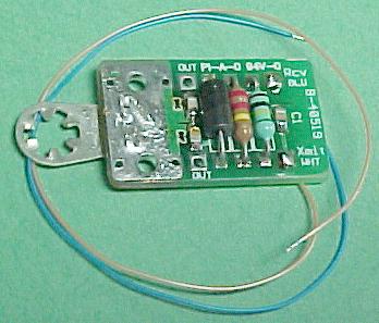 Audio output modules are available from Racorder Marine which contain the above circuitry with RF filter, output cable with female RCA style connector, and mounting lug. You may use one of these modules or make one using the guidelines below.
Unless ordered for a specific radio, the mod kit is supplied without the padding resistors R1 and R2, and the mounting lug is included but not attached to the circuit board. The mounting lug can be attached in six different orientations to accomodate many mounting situations.
The mod kit includes an output pigtail with a female RCA (phono) jack installed on one end. The mod kit board size is 0.6" x 1.0". R1 and R2 are standard readily available 1/4 watt resistors.
Having a few of these available allows you to quickly install radio mods on short notice.
Click here for pricing on radio mod kits.
|
THE SQUELCH PROBLEM
In some radios the squelch gate circuit is installed after the volume control. We like to take receive audio at the top of the volume control where a constant audio level is available for recording. In these radios the audio taken here would have the sound of always open squelch which would be quite annoying on playback, and audio taken after the squelch gate would be affected by the volume control setting. We have installed mods in these radios by taking receive audio at the speaker terminals, adjusting the padding resistors and recording level setting for optimum level where the captain is most likely to set the radio's volume control. Racorder's internal AGC circuits can handle a wide range of input levels, so this setup seems to work pretty well under normal operating conditions. However this is not ideal and would be ineffective if the radio's volume control is turned too low. |
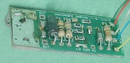 An audio output module containing a squelch gate circuit, pictured at right, is available from Racorder Marine for radios with the above described squelch problem. This allows for constant level audio recording under control of the radio's squelch circuit.
Board dimensions: 0.6 x 1.4 inches.
Click here for pricing on mod kits.
If your radio model is listed among the links at the top of this page click that link for details.
Otherwise continue below.
We suggest you study the radio's service manual and if possible take receive audio from the top of the radio's volume control so that adjusting the radio's volume control has no effect on the audio level sent to Racorder. Temporarily connect a 100K ohm resistor the volume control top terminal (not the ground or wiper terminals).
Use the radio's service manual to find transmit audio of a suitable level. Often the top of the deviation control is a good connecting point. Temporarily connect a 100K ohm resistor to this point, and the other end of this resistor to the unconnected end of the resistor attached to the volume control. Also connect a small capacitor (100pf or so) from this point to ground - this helps keep stray RF from getting into or out of the radio through the audio cable.
Run a shielded line to an RCA style jack outside the radio for connection to Racorder's input jacks.
If a Racorder unit is available, it can be connected for testing. Otherwise, connect a 100K ohm resistor between this output and ground as a load, and connect a scope or audio capable voltmeter to the output.
If using Racorder to test, connect the radio to one of the inputs of Racorder (if the number 1 input is used be sure the preamp jumpers on the audio board are set to "out") Set the input level trimmer for that input about a third of the way clockwise. Remove the jumper JP2 on the audio board so you can monitor the audio from the radio in Racorder's front panel speaker.
Notice if the squelch circuit turns off the noise on the line to Racorder; if it does not, then you have "The Squelch Problem" described in the box above. Remove the resistor from the volume control and connect it to the audio output or speaker line. Testing will have to be done with the radio's volume control set at a the point where it may be during normal vessel operations. Not ideal, but it works, using Racorder's AGC circuits to keep a relatively constant recording level, assuming the crew doesn't turn the radio's volume control all the way down.
Alternatively, a squelch gate can be inserted in the line to Racorder - we can provide a squelch gate kit which should work with just about any radio.
Watching the LED indicators in Racorder while receiving a station on the radio, adjust the value of the resistor connected to the volume control so that the input level occasionally lights the green LED and almost never lights the red LED.
If using a scope or voltmeter, adjust for approximately 100 millivolts across the 100K ohm load.
Check the setting with the reciever tuned to several different stations because diferent radios transmit with different audio levels, and some people have a stronger voice than others. Select the one with the strongest audio level for these tests.
After the receive audio resistor value is determined, transmit (using a dummy load at the antenna terminal) Āand adjust the resistor value connected to the transmit audio source as necessary to get approximately the same level as the receive test.
These levels are not critical; Racorder's AGC circuits will easily compensate for differences in transmit and receive levels. The only problem with large differences in transmit and receive levels may be the lower level being recorded at a low level in fast-paced conversations due to the AGC recovery time from a much stronger input.
Once this testing is done for a particular model of radio, then these values can be installed in other radios of the same model. ĀWe at Racorder Marine have already determined the values for many radios, and have installation kits for some. The links at the top of this page will bring you details on specific radio models for which we have prepared modification kits.