RACORDER - The Marine Black Box
INSTALLATION OF AUDIO OUTPUT IN THE ICOM M-602 VHF RADIO
Transmit resistor 1 megohm. Connect to J2 on AF board, modulation line. 5" white wire on the mod kit board.
Receive resistor 1 megohm. Connect to J6 on AF board, volume control line (red wire plugs into this). 3 1/2" blue wire on the mod kit board.
The transmit audio is taken after the low pass filter IC8-B (M5218AFP). Access at J2, the 4th pin from ground end, 2nd pin on side facing PCB edge.
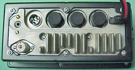
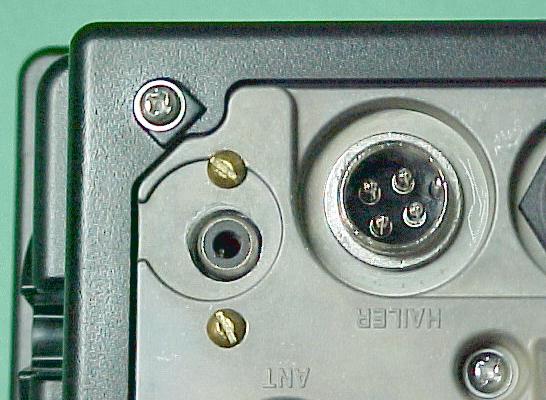
The Racorder mod kit is supplied with a pigtail which has a female inline RCA style connector on the end - this is passed through a .109" (7/64) hole drilled through the rear of the radio, and then soldered to the mod kit board.
The following photos show an installation on a radio which someone else started and then sent to us. They had mounted an RCA style jack on the rear of the radio, and we installed the mod kit to that.
PHOTOS:
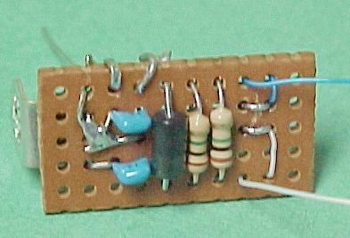
Mod kit on a perf board, component side
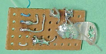
Mod kit on a perf board, solder side
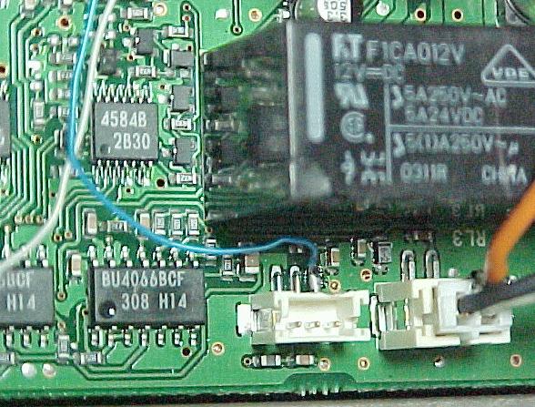
Where to connect the white (receive audio) wire
Where to connect the blue (transmit audio) wire
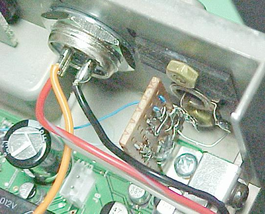
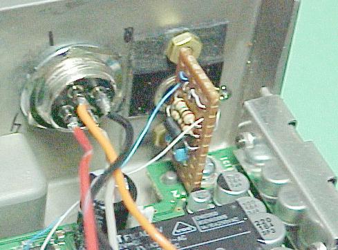
The mounted mod kit
The mounted mod kit
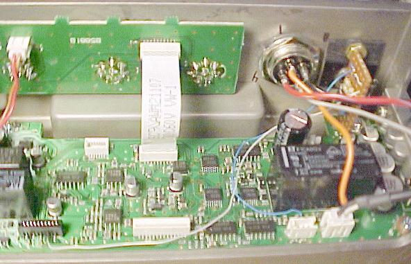
A view showing all connections
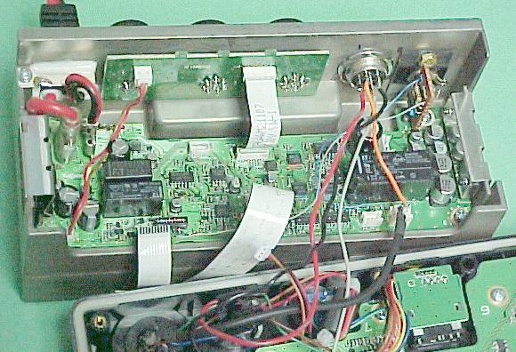
Finished radio, open
Rear of radio
Rear corner showing output jack
Updated August 12, 2004