R1 = 470K; R2 = 1.5 meg
Schematic Diagram of the Mod Kit Board
RACORDER - The Marine Black Box
| Racorder Home Page | Back to Radio Page |
Schematic Diagram of the Mod Kit Board
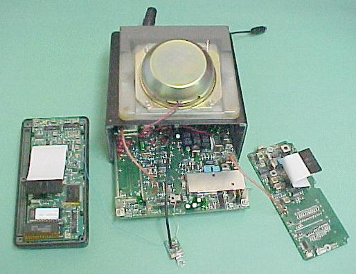
2. Remove the two screws which hold the shield plate and remove the plate.
3. Unplug the front PCB and set it aside.
4. Remove the four bottom screws and slide the speaker out.
5. Remove the two threaded spacers.
6. Remove the nuts which secure the two rear panel connectors.
7. Remove the six screws which secure the main PCB to the rear panel. Slide the main PCB out.
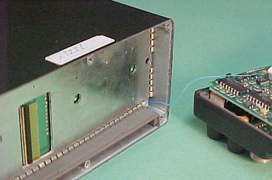
8. Drill a .109" (7/64) hole in the rear panel, 3/8" from the edge of the NMEA connector hole, right next to the label. Be sure to keep metal shavings out of the case and away from the circuit boards. The NMEA socket needs about 1/4" of space around its hole - be sure it has room to be reinstalled.
9. Pass the audio output pigtail from the rear through the hole you just drilled, and connect it tp the mod kit board, as shown.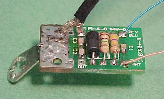
10. Solder the white (transmit audio) lead from the mod kit board to the deviation adjustment control, next to the shield box. Connect to the terminal facing toward the front of the radio which is away from the shield box, as shown.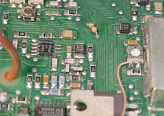
| Click this for a photo of radio ready to begin reassembly |
11. Slide the main PCB back into the case, reinstall the six screws which secure the transistors and RF module to the rear of the case, secure the connectors to the rear, and mount the speaker in place with the four bottom screws.
12. Mount the mod kit board under the right side threaded post as shown, and install the other post.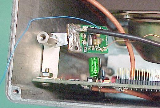
13. Route the blue (Receive Audio) wire from the mod kit board out the lower right corner of the radio, and install the front PCB, insulator, and shield plate while making sure the blue wire is not pinched anywhere and can move freely.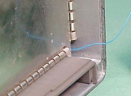
| Click this for another photo of installed front shield |
14. The blue lead coming out the front connects to the volume control circuit which is on the front panel assembly. A good place for this connection is the connector on the rear PCB of the front panel. The seventh pin from the edge near the volume control works fine. Solder the wire here as shown.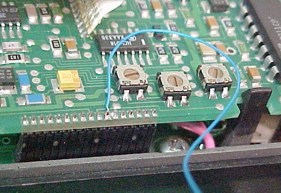
15. We're almost done! While making sure the blue lead is not pinched anywhere, reassemble the front panel to the radio.
| Click this for a photo of radio ready for final assembly |